Printed circuit boards and their assemblies (PCB & PCBA) are the core components of electronic products, and their reliability directly determines the overall reliability of electronic products. To ensure and enhance the quality and reliability of electronic products, it is essential to carry out comprehensive physical and chemical analyses of failures, identify the underlying failure mechanisms, and then propose corresponding improvement measures. MTT possesses profound technical expertise in board-level failure analysis, a complete range of analytical methods, a vast database of case studies, and a team of experienced experts, providing you with high-quality and efficient failure analysis services.
The purpose of electronic component failure analysis is to employ a variety of testing and analytical techniques and procedures to identify the failure phenomena of electronic components, determine their failure modes and mechanisms, identify the ultimate root cause of failure, and propose recommendations for improvements in design and manufacturing processes. This helps prevent the recurrence of failures and improves the overall reliability of the components.
The continuous rise in complexity and performance requirements of integrated circuits, combined with potential risks across design, manufacturing, packaging, and application stages, has led to frequent occurrences of critical failure modes such as short circuits, open circuits, leakage, burnout, and parameter drift. These issues not only result in costly device scrapping and system downtime but also often trigger disputes over responsibility among designers, foundries, packaging and testing houses, and end-users, causing significant economic losses and reputational risks.
The performance requirements for polymer materials continue to rise, while differences in understanding of high-demand products and processes between customers and suppliers often lead to frequent failures such as fracture, cracking, corrosion, and discoloration. These failures frequently cause disputes over responsibility and result in significant economic losses.
The increasingly harsh service environments of metal components place higher demands on material performance and structural reliability. However, factors such as design flaws, material defects, manufacturing deviations, or improper use can readily trigger typical failures including fatigue fracture, stress corrosion cracking, hydrogen embrittlement, creep, wear, and overload deformation.
Didn't find what you were looking for?
Consult a professional engineer immediately for your service
Didn't find what you were looking for?
Consult a professional engineer immediately for your service
Meixin Testing leverages its technological edge in constructing massive failure databases, showcasing its capabilities through comprehensive case studies, solutions for complex scenarios, partnerships with leading enterprises, and systematic intellectual property. Drawing on millions of failure analyses, it delivers precise insights into root causes, enabling inspection reports to provide robust support for clients' quality upgrades and achieve zero failures.
Didn't find what you were looking for?
Consult a professional engineer immediately for your service
Stay updated with the latest news from Maxin Testing, including technical developments, exhibitions, and events. We build on a foundation of professional testing to deliver customized solutions for our clients, ensuring quality control from the source. This empowers our clients to stand out in the marketplace and achieve commercial success.
Didn't find what you were looking for?
Consult a professional engineer immediately for your service
MTT is a nationally accredited commercial third-party laboratory. We specialize in providing testing services, technical consulting services, and solution services to clients across industries including electronics manufacturing, automotive electronics, semiconductors, and aerospace materials.
Maxin Testing operates laboratory facilities in Shenzhen, Suzhou, and Beijing, featuring multidisciplinary testing and analytical laboratories. The company pioneers an industrial hospital service model grounded in materials science engineering and electronic reliability engineering.
Didn't find what you were looking for?
Consult a professional engineer immediately for your service
Professional verification platform, delivering precise data insights to build a solid foundation of trust for investors.
Didn't find what you were looking for?
Consult a professional engineer immediately for your service
Cracking during terminal assembly? Have you encountered these pitfalls?
Release date: 2025-06-05 00:00
Share to:


In the field of precision manufacturing, even if it is a seemingly insignificant assembly cracking problem, every minor defect may become a major hidden danger of product quality and safety, resulting in tens of millions of losses.

Image

We found that a stamped copper strip after stamping, in the assembly process found that there are terminals cracking, cracking has occasional irregularity. This seemingly ordinary failure is behind the potential major hidden dangers in the rolling process.

This article will take you to analyze this case in depth, starting from the cracking phenomenon of the spouse, gradually uncovering the truth about the surface layering defects of the material, and exploring the reasons 
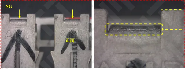
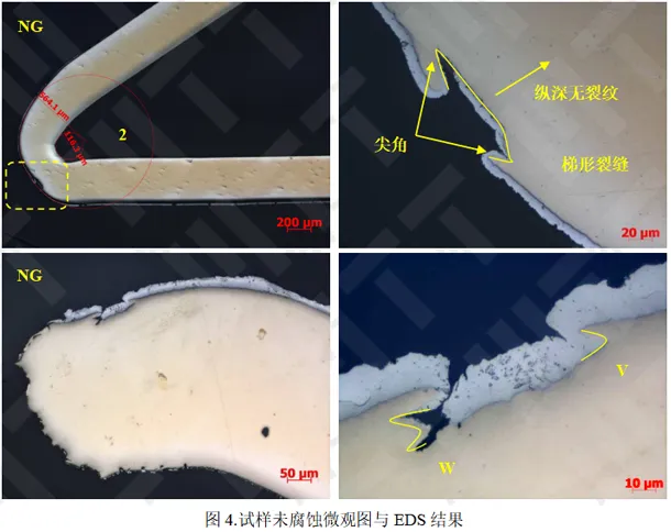
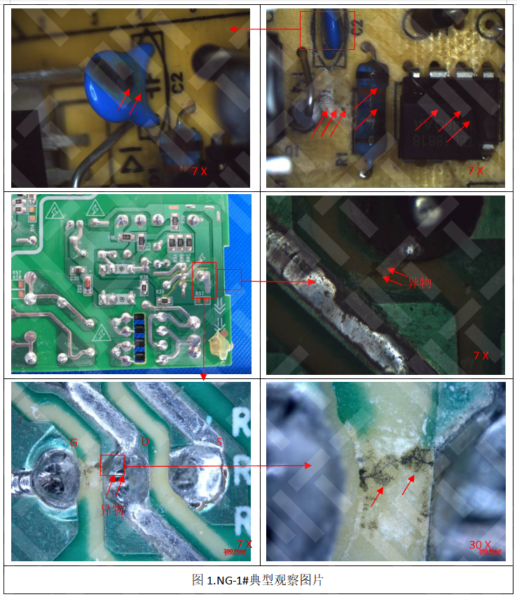
behind it.


1. Low observation.

It can be seen from the figure that the specimen NG crack is located in the bending part of the terminal, near the center of the curved arc, close to the front of the terminal, and the bending part of the crevice is the most severe position in the bend. The crack has a certain width 
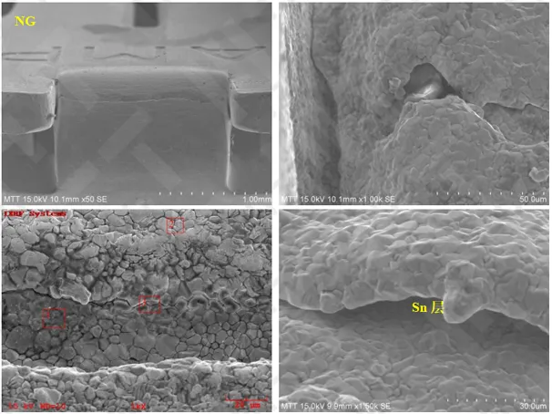
and depth, and the crack edges are visible layered gap distribution.

Image

2. Surface analysis

The two edges of the crack have overlapping characteristics, and the granular tin plateding distribution is visible in the layered gap of the crack, which indicates that the cracks have existed before the tin plating. The silhouette of the edge of the crack coincides, indicating that the crack position is intact before bending, that is, the crack is 
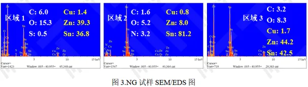
caused by bending when punching. Spectroscopic analysis shows that the local surface Zn content of the coating is high.

Image

Image

3. Metamorphic analysis

It can be seen from the figure that no obvious layering and other defects have been found at the bending, cracks can be seen at the bending, the cracks are trapezoidal, and there is no cracking extension at the bottom of the trap. Before plating Sn, the cracks already existed. The other crevice can see the "W"-shaped sharp angle, and the "W" sharp angle can be seen with the overlap contour of the gap, indicating that after the sharp angle of the crack here is stretched, the original layered gap is
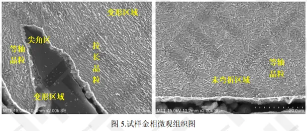
 open.

Image

Figure 5 shows the gold phase diagram after the corrosion of the specimen. It can be seen from the figure that the matrix metal phase can be seen in the distribution of twin crystals, the grain is fine, and the grain uniformity is better. In the bending deformation area, it can be seen that the grain is elongated, and the sharp angle area is close to the outer surface tissue, the core area of the substrate core and the grain in the uncurved area is still in an equal axis, that is, no more obvious
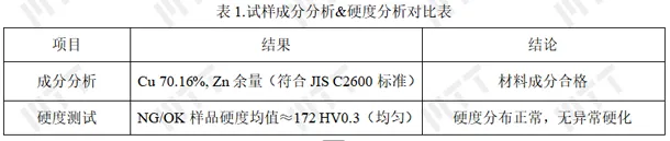
 deformation occurs.

Image

4. Ingredient Analysis & Hardness Analysis

Table 1 shows that the chemical composition of the material meets the requirements of the C2600 grade chemical composition in JIS H3100-2018, and the cross-section hardness distribution is more uniform.

Image


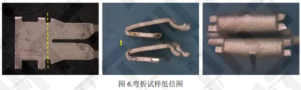
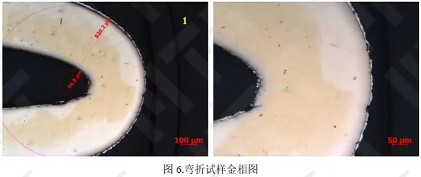
5. Bending analysis

Take OK samples along the bending process, low observation, as shown in Figure 6. It can be seen from the figure that the tin-plated layer of the bending and tensile surface is cracked, and the brass substrate is exposed. In order to observe whether the substrate is cracked, a metallographic analysis of the specimen is required.

Image

The metallographic analysis of the bend sample will be bent, as shown in Figure 6. It can be seen from the figure that the tensile surface matrix of the bending part does not see the crack, and the compression surface can be seen to extend the thickness of the belt along the belt, and it can be seen that the tensile surface has a good extension performance under a certain bending and curvature when bending the curvature.

Image

6. Discussion and Summary

The study believes that in the plastic deformation stage, copper and copper alloy grains will be slipping and forming steps, grain orientation, size is different, the degree of distortion is different, will form different surface conditions, such as smooth, wrinkles and cracks. It can be seen from the outline of the edge of the crack, the crack can be partially coincident, that is, the crack belongs to the external force to be separated. The metallographic phase can be seen, compared with the significant plastic deformation of the grain on the surface of the trapezoidal crack subsurface, the grain of the tissue of the sharp angle of the trapezoidal crack near the outer surface of the tension is not significantly elongated, that is, no more obvious plastic deformation occurs. After the crack subsurface is opened, the crack does not extend further in the direction of thickness and the bending test can prove that the material has excellent anti-stretching plastic deformation ability. The bending structure of the NG specimen has a layering defect, which is located in the subsurface layer, and the layering is first broken during the bending process.

To sum up, it can be seen that the defect here is the deep pressure on the surface of the strip, because the material has excellent plasticity, the subsequent rolling deformation, the tape extends at the crushing site, forming a layered defect.


Comprehensive analysis can be seen, the material subsurface has a layered defect, is the main reason for the cracks in the bending when the punching.


Relevant cases
Still failing despite meeting IPC standards? The OSP film thickness tolerance vulnerability overlooked by 90% of factories
After undergoing two reflow temperatures, OSP pads exhibited severe solderability issues during wave soldering. Reducing the reflow temperature resolved the solderability problems. This paper analyzes the failure causes and mechanisms of solderability defects on OSP pads and proposes improvement recommendations.
The Truth Behind the 30% Surge in FPC Lead-Free Failure Rates | The “Invisible Killer” of Consumer Electronics
A certain FPC exhibited routing shallowing at certain locations, with both the edges and central areas of the defective samples showing this phenomenon. This paper will conduct a systematic failure analysis to identify the root cause of routing shallowing in the FPC.
Silicone Exceeding Limits = EU Sales Ban? With Global Regulations Tightening, Is Your Product Compliant?
Siloxanes are a class of organosilicon compounds containing Si-O-Si bonds, widely used in rubber, detergents, polishes, adhesives, sealants, and other fields. Due to the environmental and health risks associated with certain siloxanes, numerous countries and regions worldwide have enacted regulations to control their use.
Save Millions! Practical Tips for Avoiding Pitfalls in Metal Material Selection (Part 2)
In the previous article, “Choosing the Wrong Metal = Burning Money! A Guide to Avoiding Pitfalls in Metal Material Selection for Electronics (Part 1),” we established a knowledge framework for metal material properties and applications, and outlined the core steps for scientific material selection. However, theory must be tested by practice. This article will focus on the practical aspects: How can advanced inspection technologies provide reliable data support for material selection decisions? How can performance and cost be skillfully balanced in projects? Real-world case studies will reveal the consequences of improper material selection and the solutions to address them.
Choosing the Wrong Metal = Burning Money! A Guide to Avoiding Pitfalls in Metal Selection for Electronics (Part 1)
In electronic products, the selection of metal components directly impacts product performance, safety, and lifespan. From smartphone casings to aircraft engine blades, the scientific selection of metal materials stands as a core element in technological R&D. This article will explore the cost-effectiveness considerations in metal material selection in two parts, integrating laboratory testing techniques with engineering practice.
Flux compatibility issues with PCBA can actually lead to such severe consequences?!
A PCBA board for an audio product (using wave soldering) suffered burnout during operation. When using flux variant A, failure rates were high; after cleaning, the rate decreased slightly. Switching to flux variant B reduced the defect rate to zero. This paper will employ a series of professional testing and analytical methods to identify the root cause of the failure.
Online Customer Service
Business Consultation
Free Consultation
Report Inquiry
Back to Top
Contact Us
  • *Name:
  • *Contact:
  • *Email:
  • *Company/Organization/school:
  • *The location:
  • *Message information: