+86-400-850-4050


Didn't find what you were looking for?
Consult a professional engineer immediately for your service


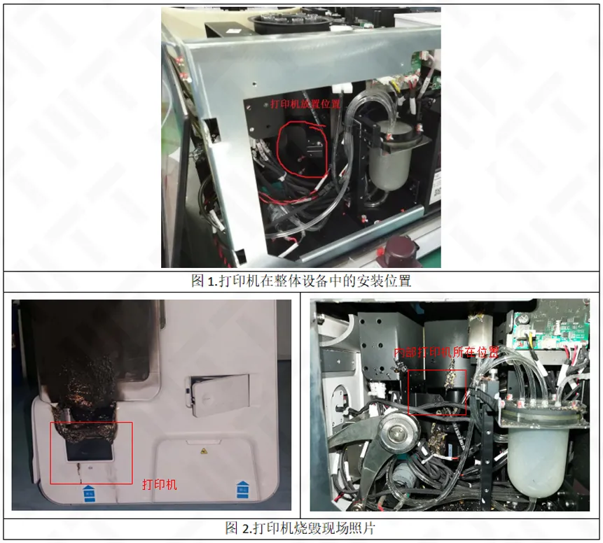
A certain type of thermal printer suddenly burned in standby state, and the fire point is located in the internal motherboard area. The function is restored after the replacement of the new equipment, but the cause of the failure needs to be identified. Check the sample includes burning the whole machine, good product machine and motherboard, through systematic analysis, and finally lock the source of the fault for the Cl element caused by the corrosive short circuit, the following is the key analysis process and conclusions.
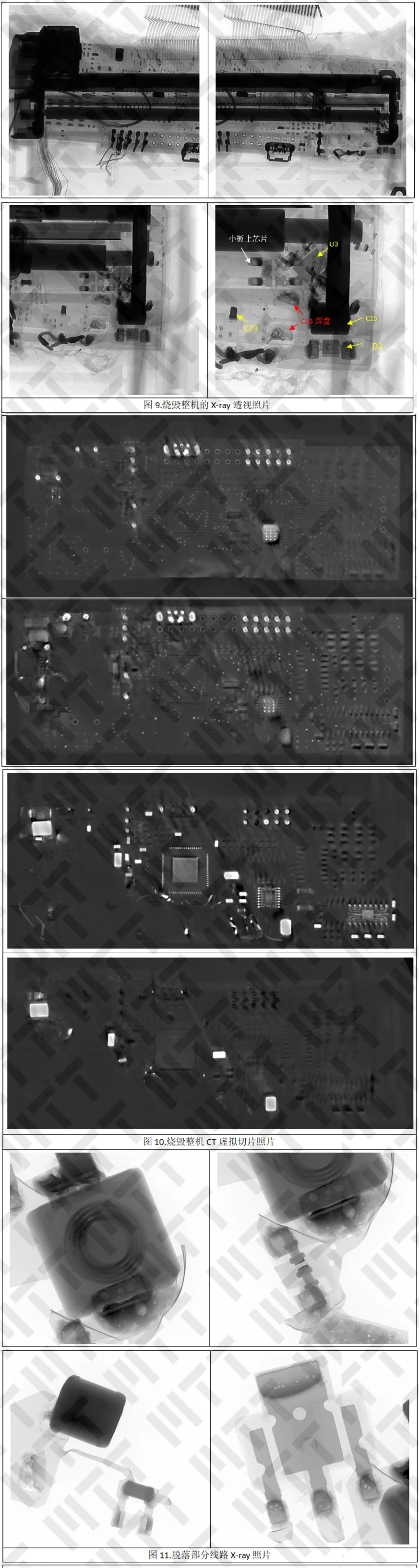
1. Appearance Check & X-ray Perspective
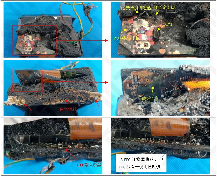
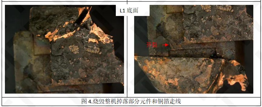
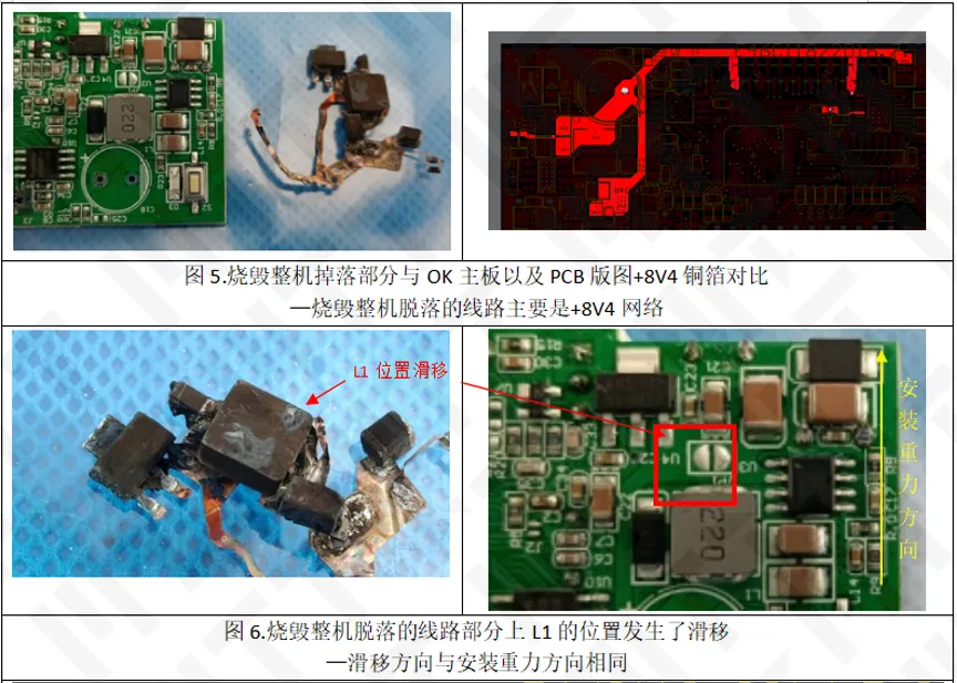
The appearance of the burned printer burned very serious, the motherboard surface, especially the edge of the open fire, the plastic shell also ignited the open fire on the edge of the motherboard and the plastic shell there are traces of open fire burning, some components (such as L1 inductance, J3 FPC connector) fell off, +8V4 power network line fracture, but FPC only one side of the obvious burn.
PCB has no single burn-through point, and the overall phenomenon of uniform overheating is uniform, excluding the possibility of local short circuit causing burning.
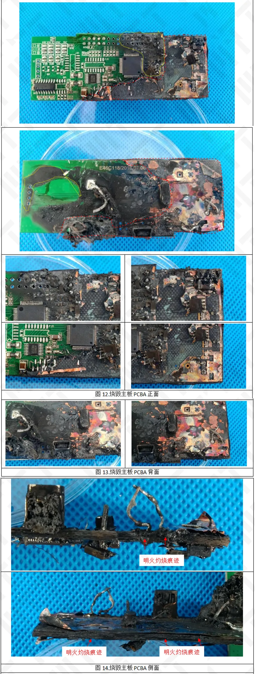
3. Dismantling inspection
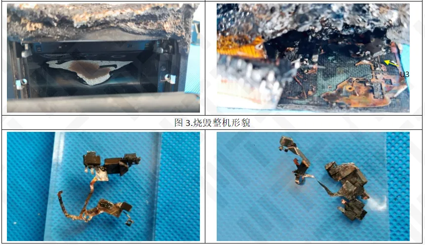
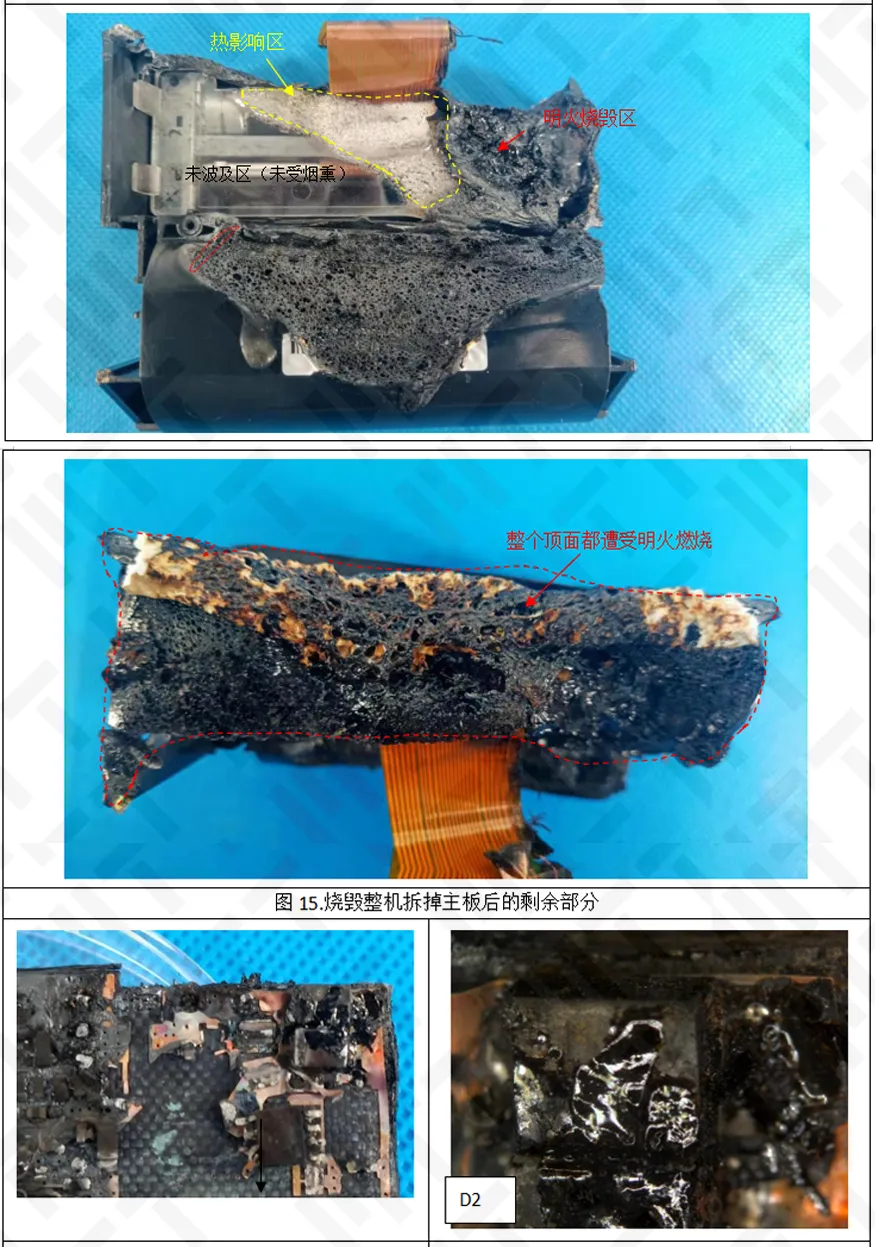
Burning area is concentrated in the power circuit (VINPUT, INPUT, +8V4 and GND network), the motherboard surface has not found obvious copper foil melting and PCB board burning pits or holes and other small areas of serious burning characteristics, the motherboard surface presents a large area of overheating phenomenon, the edge of the board has an open fire burning traces. There are long-distance smoky marks on the back of the motherboard.
The rest of the burn can be observed on the rest of the machine that is the most serious, which roughly corresponds to the location of the part of the +8V4 network. The transparent plastic inside has a significant heat impact area, but there is no trace of smoke in the area.
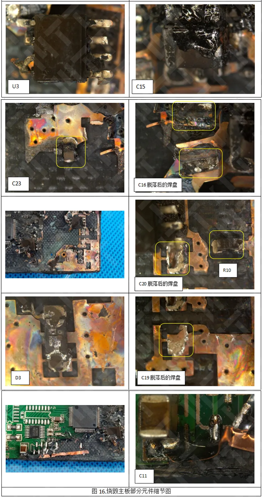
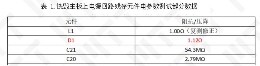
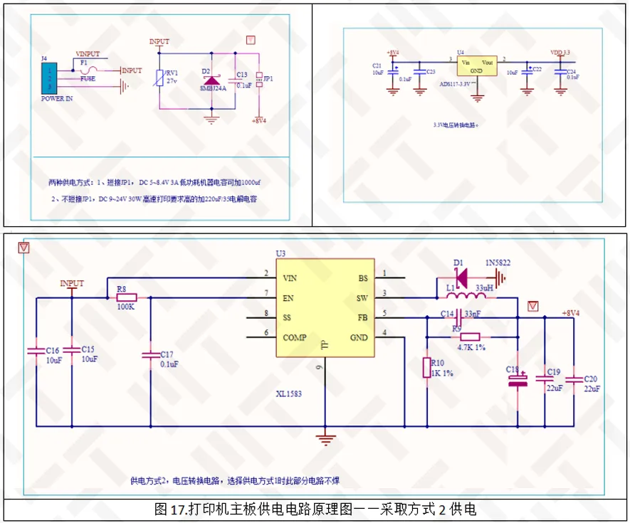
4. Electrical parameter testing of residual components in power supply circuit
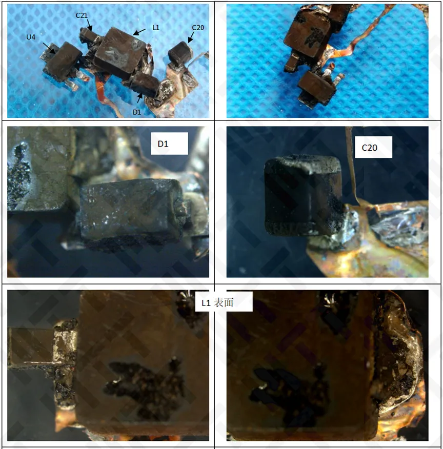
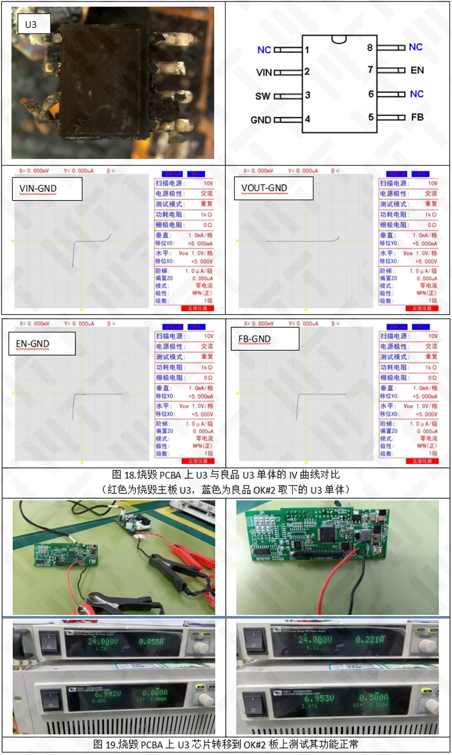
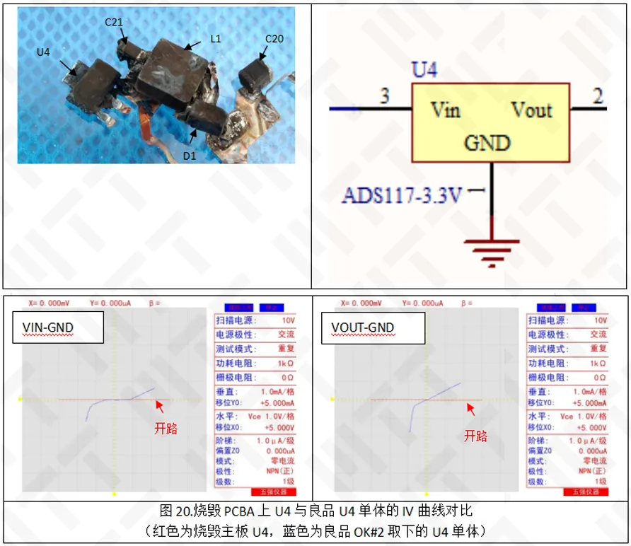
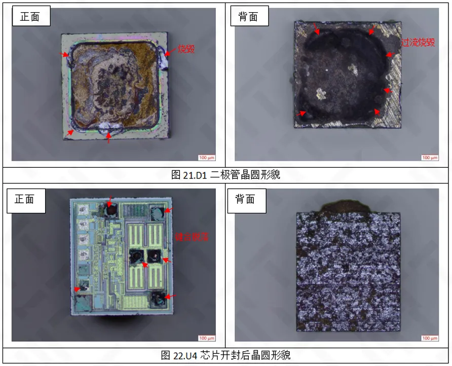
The D1 diode in the power circuit is short-circuited, the U4 chip is open-circuited, and the impedance or pressure drop of other components is normal. The U3 chip IV curve is normal, but the test function of transferring to the good plate is also normal, indicating that the U3 itself is not damaged.
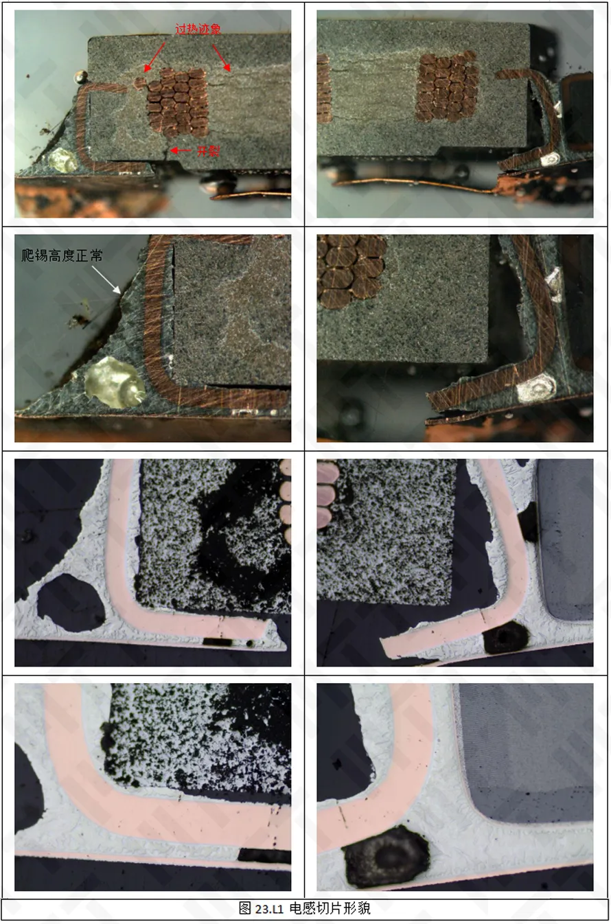
5. Open and slice
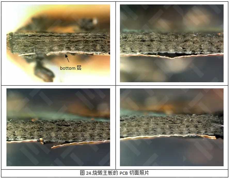
D1 diode wafer overcurrent burned, U4 chip bonding off, L1 inductor internal signs of overheating but welding normal. There is no obvious burning point on the PCB board section of the motherboard, but the glass fiber near the top layer burns more seriously.
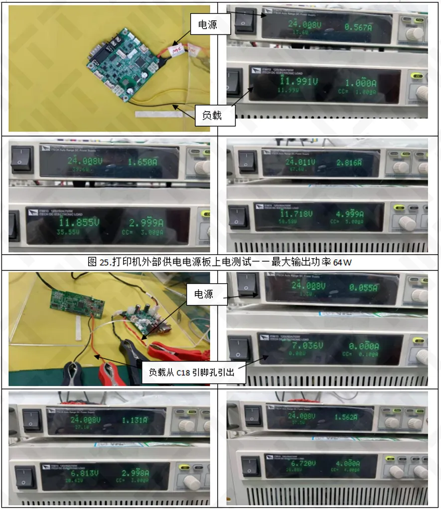
6. Power board and good product motherboard power test
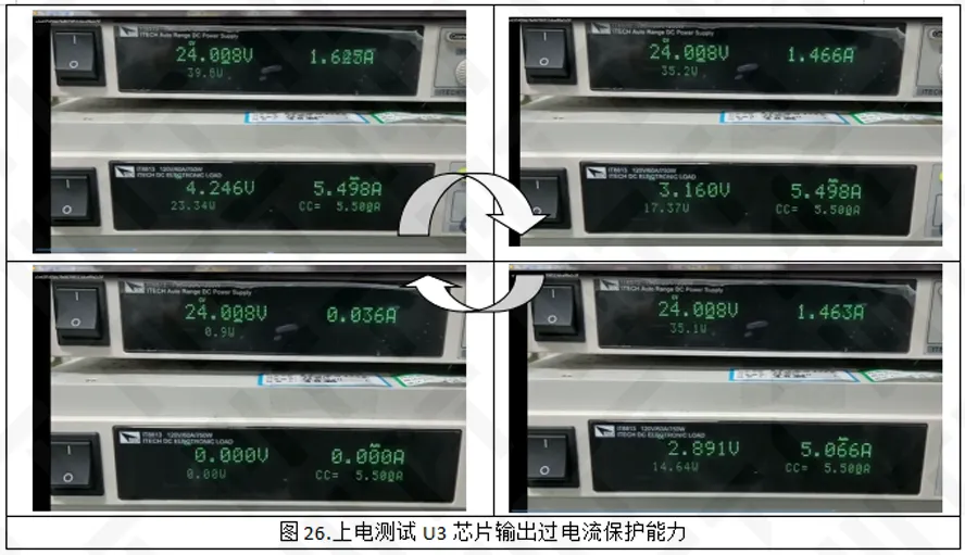
The power supply plate (design power supply current 5A) outside the printer was tested and found that its output voltage decreases as the current increases, and when the output current reaches 5.5A, the output voltage drops to 11.68V, and the output power reaches a maximum of 64W. Take the OK#1 motherboard, lead the wire connection load from the C18 pin, test the output overcurrent protection ability of the U3 chip, and find that when the U3 output voltage should be 7V, rather than the nominal 8.4V. Overcurrent protection is triggered when the output current reaches 5.5A. When the output current of U3 reaches 5.5A, the output voltage drops rapidly, the voltage drops to about 2.8V, and the output current is cut off to cycle.
7. Good product motherboard simulation test
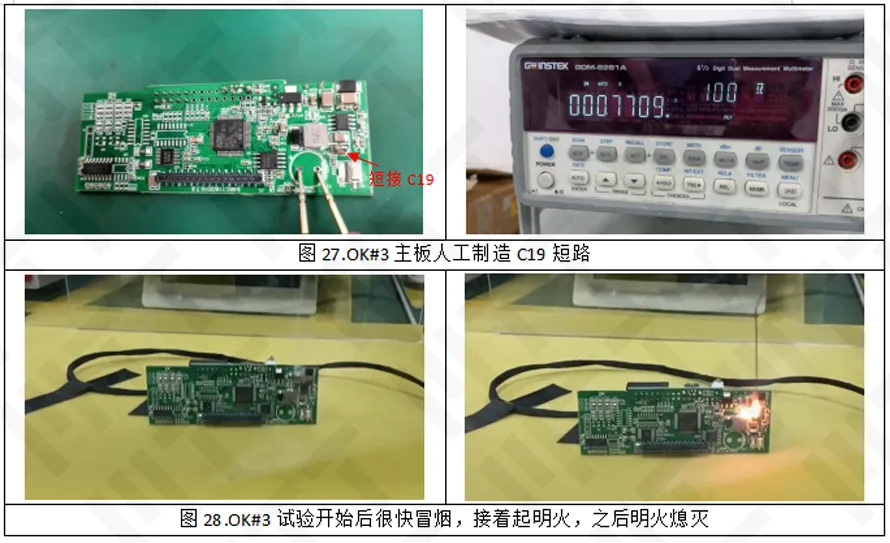
Because the C19 and C16 on the burned motherboard disappear, assuming that they have a short circuit, whether it will cause the burner. After the L1 short JP1 printer can work properly, at this time if the back end of the short circuit can cause the burner. To test the above assumptions, the following tests were designed:
OK#3 motherboard, short access to C19, after the power on the smoke after the fire, the burned components for the U3 chip, and the burning of the machine does not match.
OK#4 motherboard, after short access to C16, no burn occurs after powering. Circuit short circuit protection start.
OK#5 motherboard, move L1 to burn the position on the motherboard, after the power on the indicator light is normal; after the short +8V4 to GND, power again, no burn, the power output power is up to 22.6W, and then the drop is stable at 2.1W, which shows that the short circuit protection in the circuit has been started.
8. Simulation test
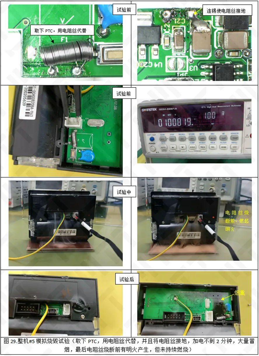
OK machine #5, remove the PTC, replace it with resistance wire, and ground the resistor wire, after powering, a lot of smoke, and finally the resistance wire burns before the open fire, but does not continue to burn. After the test, the inspection is opened, the PCB board has a smoky trace on the back, and the smog traces cover the area and the failure sample of the motherboard burn area overlap.
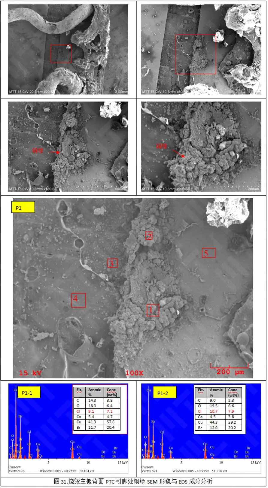
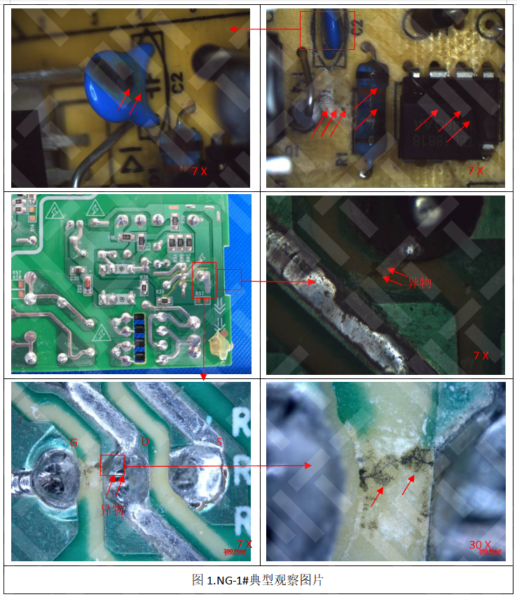
9. Burning the motherboard PTC pin check
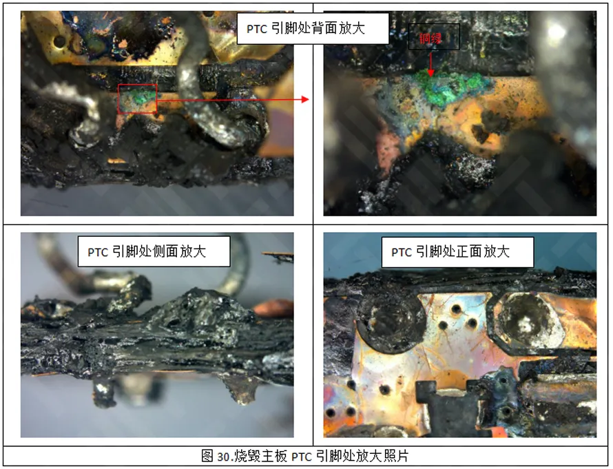
Therefore, it is inferred that the initial smoke starting point on the PCB board is at the PTC pin on the back of the PCB. Figure 30 shows that the PCB board at the pinhole of PTC has obvious traces of open fire burning. The enlarged inspection at the PTC pinhole of the burned motherboard. The copper green is found at the PTC pin on the back of the motherboard. Copper green is the product of copper produced under the combined action of copper, carbon dioxide, water and oxygen under wet conditions. The production of copper green indicates that the copper skin is corroded here. EDS tested the copper green and found that it contained corrosive elements Cl and Br, which may come from flux residue, copper-green adjacent areas, and Cl elements were mainly detected in copper-green. The presence of the Cl element accelerates the formation of copper green. Therefore, it can be speculated that the PCB board at the PTC pin should have a corrosive foreign body containing the Cl element, and the foreign body containing the Cl element corrodes the copper skin, causing the PTC pin to the short circuit burning of the ground wire.
10. Summary
The burned printer fire point at the PTC pin on the back of the motherboard, where copper-skin corrosion-forming products were found, and the abnormal corrosive element Cl was detected on the copper-green.
Foreign objects containing Cl corrode the copper skin, causing the PTC pin to burn short-circuited the ground wire.
This article is full of goods, come and comment to share your harvest!
We will be on May 30, 2025.
Draw 3 lucky readers and send out the failure analysis case book!


Maxin Testing Laboratory
Learn more about our company

Electronic Manufacturing Information Hub
See more exciting case studies

Video Channel
Watch more exciting videos


 Buildings A1, A3, and A5, Peking University Science and Innovation Park, Songbai Road, Bao'an District, ShenzhenBuilding 3, Xinyao Valley, 415 Changyang Street, Suzhou Industrial Park, Suzhou City1st Floor, Building 4, No. 39 Anzhi Street, Suzhou Industrial Park, Suzhou City